Comparison of basic gasification processes

Uninterruptible power supply units

Uninterruptible power supply units (UPS) are designed for protecting computers and other electronic equipment against damages caused by interruptions of electric power supply.

The definition of the term «uninterruptible power supply unit» complies with GOST 264160-85. According to GOST 27699-88, the term «uninterruptable power supply system» is used.

The basic function of uninterruptible power supply units is to supply high-quality electric power to customers.

Likewise, gas generation plants are designed for supplying customers with high-quality gas as an energy carrier.

The basic types of uninterruptible power supply units are the following:

Off-line uninterruptible power supply units

Line-interactive uninterruptible power supply units

On-line uninterruptible power supply units

Comparison of uninterruptible power supply units (UPS)

Off-line UPS

The characteristic features of off-line uninterruptable power supply units are the following. In the normal operation conditions, the power supply of the connected electric load is provided directly from the electrical network. The input voltage is filtered by the passive filer of the uninterruptable power supply unit in order to suppress high-voltage pulses and electromagnetic interference. If the input voltage is outside of the specified range, or if the power supply from the electrical network is interrupted, the electric load is automatically connected to the output of the inverter which converts the direct voltage of the accumulator battery into the alternating output voltage with specified parameters. When the input voltage is normal, the switching device connects the electric load to the electrical network.   The commercial price for the uninterruptable power supply unit of 1600 VA is 322 US dollars or 0.2 US dollars per 1 VA.

Line-interactive UPS

As is shown in the diagram above, the circuit of a line-interactive uninterruptable power supply unit contains the same elements as the circuit of an off-line uninterruptable power supply unit, and additionally, a buster transformer with step-by-step voltage control, providing the power supply of Category VI according to IEC classification. In the normal operation mode, such uninterruptable power supply units do not ensure the stability of the output frequency. The passive filter of the unit provides filtration of the input voltage. If the input voltage is interrupted, the electric load is connected to the output of the inverter, as in the circuit of an off-line uninterruptable power supply unit.

The commercial price for the uninterruptable power supply unit of 1550 VA is 571 US dollars or 0.368 US dollars per 1 VA.

On-line UPS

On-line uninterruptable power supply units, as units with double-voltage conversion, are used for power supply of servers in information networks, high-performance workstations of local area networks, and other equipment for which high-quality electric power is required.

According to the diagram shown above, the uninterruptable power supply unit operates as follows.

First, the alternating input voltage is converted into intermediate direct voltage by the rectifier; than the direct voltage at the output of the rectifier is converted into the alternating output voltage by the inverter. If the input voltage is interrupted, switching operations for connecting the electric load to the accumulator battery through the inverter are not required, as the electric load is permanently connected to the inverter. So, the time for performing switching operations is excluded.

The commercial price for the uninterruptable power supply unit of 1500 VA is 752 US dollars or 0.5 US dollars per 1 VA.

Comparison of gasification processes

Off-line gasification

Gasification efficiency:

60 … 70 %

Efficiency of electric power generation:

14 … 24 %

Electric power generation (kW·h/1 ton of fuel):

300 … 600

Gas composition:

The gas composition is  dependent, to a high degree, on the composition and moisture content  of fuel (F), type of blast (B), temperature conditions, and the gasification process used in the gas generator (a direct gasification process or an inverse gasification  process).

This gasification process is characteristic by the high content of resins in the generator gas.

It is required to determine the costs of other gas generation plants if the cost of one of the plants is known:

According to the offer, the cost of a gas generation plant of 2500 kW is 168,750 US dollars, or C1 = 67.5 US dollars per 1 kW.

Line-interactive gasification

Gasification efficiency:

70 … 80 %

Efficiency of electric power generation:

20 … 30 %

Electric power generation (kW·h/1 ton of fuel):

350 … 700

Gas composition:

The gas composition is  dependent, to a high degree,  on the composition and moisture content  of fuel (F), type of blast (B), temperature conditions, and the gasification process used in gas generators 1 and 2 (a direct gasification process or an inverse gasification process).

This gasification process is characteristic by the high content of resins in the generator gas.

It is required to determine the correcting factor K2 for the cost C2 = K2 ´ C1 (K2 > 1).

On-line gasification

Gasification efficiency:

80 … 85 %

Efficiency of electric power generation:

28 … 34 %

Electric power generation (kW·h/1 ton of fuel):

600 … 1200

Gas composition:

The gas composition is dependent on the type of blast (B), and is low-sensitive to the composition and moisture content (up to 50 %) of fuel (F).  The quantity (in the range of 20 … 100 %) and quality of gas can be controlled.

This gasification process is characteristic by that resins in the generator gas are virtually not present.

It is required to determine the correcting factor K3 for the cost C3 = K3 ´ C1 (K3 > 2).

General-purpose combined gas-generating unit

GUK-1-5-M-2

Gas-generating units of this type are designed for gasification of organic (hydrocarbon) solid fuels with the characteristics that comply with the requirements for the composition and parameters of fuel specified in Table 1.

Table 1 Basic parameters and composition of fuel

The process of gasification of solid fuel consists in complete conversion of the fuel chemical energy into gas chemical energy. The efficiency of this process primarily depends on the design characteristics of the gas-generating unit, as the optimal characteristics provide the possibility to perform fuel gasification on the basis of new technologies and principles.

            Due to the specific design of the gas-generating unit, which consists of seven process sections, each of which is designed to perform its specified functions, it is possible to control the gasification process in the completely automated operational mode in accordance with the control programs specific for each fuel type. The general arrangement drawing of the gas-generating unit is presented in Figure 1.

            Before describing the gasification process and the gas-generating unit potential, it is reasonable to demonstrate that the gas-generating unit is suitable for operation as the basic element of a unified solid-fuel power-generating plant.

            The block schematic diagram of the solid-fuel power-generating plant on the basis of a GUK-1-5-M-2 gas-generating unit is shown in Figure 2. The block schematic diagram presents flow paths for fuel, air, generator gas, heat transfer medium, and water for damping of fuel and for fire extinguishing, as well as all interconnections between the elements of the power-generating plant. There are various alternative designs of such a power-generating plant, of which only one alternative design is discussed below.

Figure 1. Gas-generating unit GUK-1-5-M-2

Component parts list for Figure 1

1 Charging fuel

2 Cover of the fuel section

3 Branch pipe for receiving fuel (this branch pipe is connected to the outlet of a belt-type conveyor with conveyor flights)

4 Shaft of the conveying screw

5 Sprocket of the conveying screw drive

6 Casing of the conveying screw for feeding charging fuel (conveying screw No. 1)

7 Mold tube of the conveying screw No. 1

8 Fuel receiver

9 Fuel collector

10 Flange connection

11 Explosive valve

12 Branch pipe for feeding unrefined generator gas

13 Sensor for detecting the lower level of fuel in the mixture section

14 Gas-supply pipe

15 Casing of the air distributor for the gas generator No. 2

16 Starting burner of the gas generator No. 2

17 Unrefined generator gas 18 Flange connection

18′ Manhole for installing sensors

19 Flange connection

20 Branch pipe

21 Casing of the sealing section

22 Branch pipe for discharging unrefined generator gas

23 Starting burner of the gas generator No. 1

24 Ash receiver

25 Access manhole

26 Access manhole

27 Ash-removing conveying screw

28 Access manhole

29 Sprocket of the ash-removing conveying screw drive

30 Casing of the air distributor for the gas generator No. 1

31 Air 32 Branch pipe for feeding air

32′ Casing of the ash removal section

33 Flange connection

34 Temperature sensor

35 Gas collector of the gas generator No. 1

36 Flange connection

37 Explosive valve

38 Gas collector of the gas generator No. 2

39 Generator gas

40 Branch pipe for discharging generator gas

41 Explosive valve

42 Temperature sensor

43 Air

44 Branch pipe for feeding air

45 Sensor for detecting the upper level of fuel in the mixture section

46 Casing of the gas distributor

47 Backup (additional) branch pipe

48 Sensor for detecting the lower level of fuel

49 Sensor for detecting the upper level of fuel

50 Mold tube of the conveying screw No. 2

51 Casing of the conveying screw for feeding standby fuel (conveying screw No. 2)

52 Sprocket of the conveying screw drive

53 Branch pipe for receiving fuel (this branch pipe is connected to the outlet of a belt-type conveyor with conveyor flights)

54 Standby fuel

55 Sprocket of the metering device drive

Note

             In Figure 1, there are shown no load-bearing elements, service platforms, elements of the cooling system, and elements of the fire-extinguishing system of the gas-generating unit.

Figure 2. Block schematic diagram of the solid-fuel power-generating plant (example)

  1. The gas-generating unit GUK-1-5-M-2 is designed for gasification of organic solid fuels with parameters specified in Table 1. Using this gas-generating unit, it is possible to gasify low-grade solid fuels which can be ineffective or unacceptable for other gas-generating units.

            The productivity of the gas-generating unit is 3000 nm3/hour when producing generator gas with a lower heating value of  Qwl= 1500 kcal/nm3 (6.285 MJ/nm3) in the nominal operating mode.

            The thermal power of the gas-generating unit in the nominal operating mode is calculated as follows:

where:            

On inserting the parameter values in Equation (1), the thermal power of the gas-generating unit is determined as follows:

  1. Fuel for the gas-generating unit shall be reduced to the sizes specified in Table 1. It is possible to use a uniform fuel or a mixture of different fuels with known properties and chemical composition which have an effect on the fuel consumption.

            To determine the consumption of fuel with the parameter values stated in Item 1, the calculations specified below shall be performed.

            The efficiency coefficient of the gas-generating unit is h = 0.85, that is, solid fuel to the extent of 85 percent converts completely into generator gas.

            Knowing the chemical composition of the charging fuel, it is possible to calculate the lower heating value of the fuel as follows:

Example

            To produce 3000 nm3/hour of generator gas with a lower heating value of 1500 kcal/nm3, it is necessary to gasify brown coal at consumption calculated by using the following equation:

where:

Inserting the numerical values into Equation (3), the consumption of charging brown coal is determined as follows:

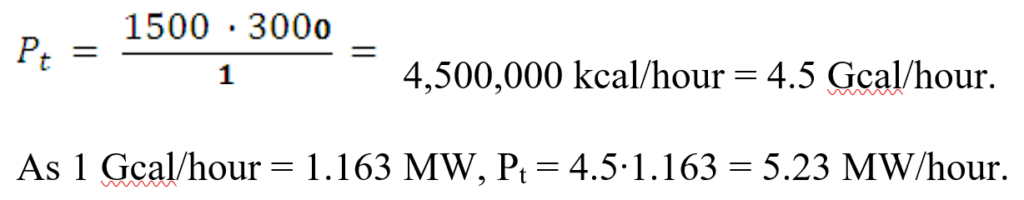
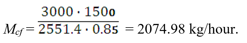
That is, to produce 3000 nm3/hour of generator gas with a lower heating value of 1500 kcal/nm3, it is necessary to gasify about 2075 kg/hour of brown coal with known composition.

            This calculation procedure is suitable for any organic solid fuel or a mixture of solid fuels. In the case of a mixture of solid fuels, the lower heating value of the mixture is determined as the total of the lower heating values calculated for each of the components of the mixture.

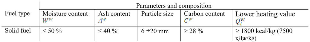
  1. As stated above, it is possible to gasify solid fuels of any type, including brown coal and black coal, provided that the fuel does not conglomerate at high temperatures of 1100 ÷1300 °C.

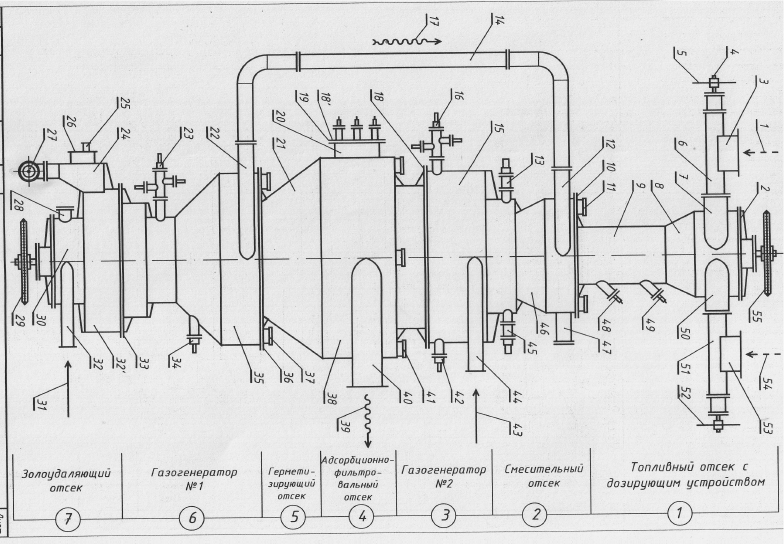
            The gas-generating unit GUK-1-5-M-2, shown in Figure 1, provides the feasibility of the gasification process, according to which it is possible to produce, from any solid fuel, the specified volume of generator gas (for example, 3000 nm3/hour) with the specified lower heating value (for example, 1500 kcal/kg) and with the same chemical composition, that is, 28 ÷ 32 percent CO, 20 ÷ 24 percent H2, and 46 ÷ 48 percent N2.

            It is shown in Figure 1 that the gas-generating unit contains two independent inlets for fuel, that is, the inlet for charging fuel (1) and the inlet for standby (additional) fuel (54). This design allows fuels of different types, with different properties, and at the specified ratio between the fuel rates to be fed into the gas-generating unit. The process of mixing the charging fuel with additives or another fuel is accomplished in the fuel section of the gas-generating unit due to the rotation of the shaft of the metering device with a sprocket-based drive (55).

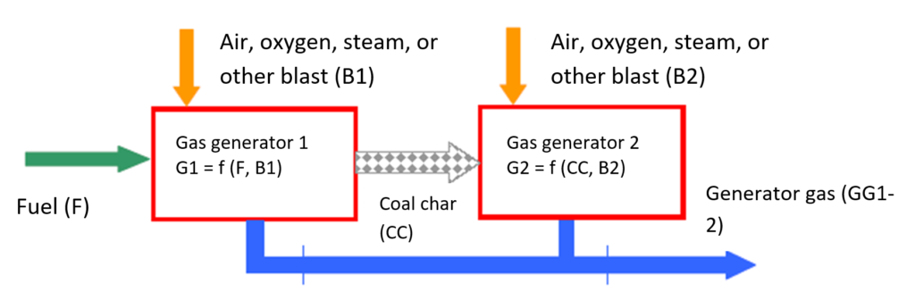
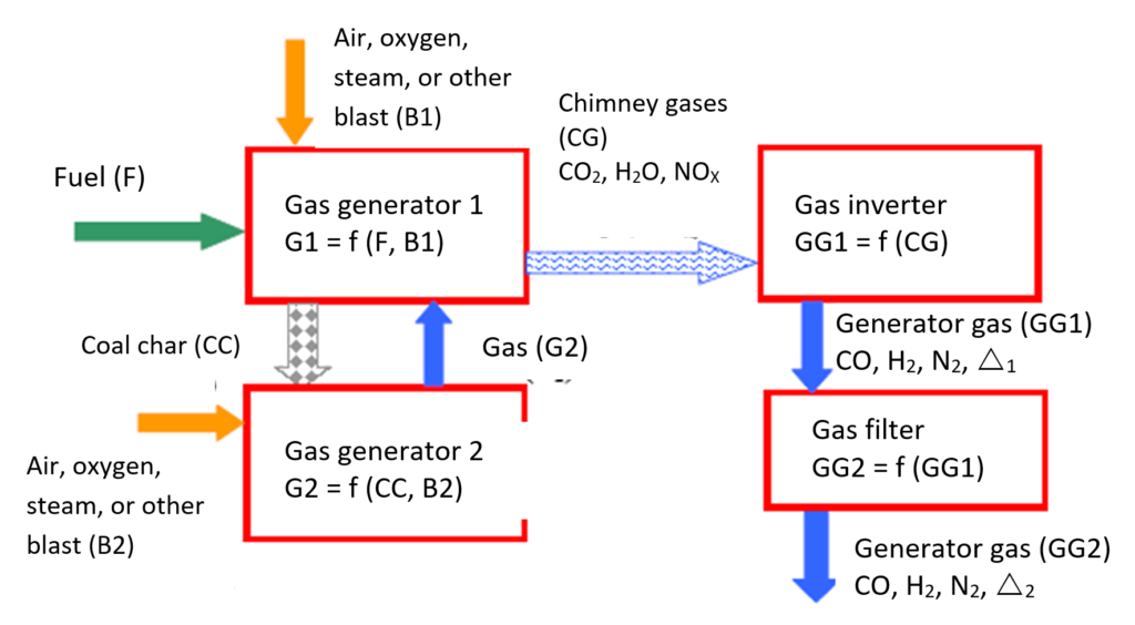
            Gas generators No. 1 and No. 2 operate in parallel-series arrangement, according to which the final generator gas (39) is produced by the gas generator No. 2 only. The unrefined generator gas (17), which is produced by the gas generator No. 1, is fed into the mixing section of the gas-generating unit and used for enriching the charging fuel to be fed into the gas generator No. 2.

            This technology allows the thickness (depth) of the reducing zone of the gas generator No. 2 to be increased in several times, and, as a result, it is possible to reduce all combustion products, which are formed in the burning area of the gas generator No. 2, as follows:

            C + CO2 = 2CO;

            C + H2O = CO + H2;

            C + 2NO = N2 + CO2.

            Low-temperature coke filling the whole gas filtering section of the gas-generating unit is cooled by a special cooling device and converted into an effective absorbing-filtering layer, acting as an additional gas cleaning element. The whole generator gas produced passes through this element. The regeneration of the low-temperature coke goes on at all times in the process of gasification of raw charging fuel.

            The low-temperature coke, on absorbing and filtering all impurities in the generator gas, drops down and is used as working fuel for the gas generator No. 1. The impurities are subjected to high-temperature treatment at 1100 ÷ 1300 °C.

            This gasification process provides the possibility to dispose, by thermal decomposition, toxic and contaminating substances, herbicides, pesticides, pharmaceutical waste, and other foreign substances. Virtually all chemical substances in solid, liquid, or gaseous state, with the possibility to be disposed by thermal decomposition, cannot entry the external environment due to using this ecologically clean gasification technology on the basis of the proposed gas-generating unit.

            Depending on the chemical composition of the charging fuel and the properties of substances to be disposed, it is possible to determine the optimal ratio between the quantity of chemical impurities and the quantity of the charging fuel . If these quantities are presented in weight units, this ratio is in the range from 0.5:10 through 1.5:10.

            The chemical substances, decomposed in the high-temperature zone of the gas generator No. 2, enter the low-temperature filtering section, which prevents reverse reactions with the decomposition products, and together with the low-temperature coke enter the high-temperature zone of the gas-generator No. 1.         The decomposition products after repeated thermal action convert into neutral chemical compounds formed in the result of reaction with chemical elements present in the fuel ash, or into individual neutral chemical elements. These chemical compounds or elements together with the fuel ash pass through the cooled ash removal section of the gas-generating unit and are fed by the conveying screw (37 in Figure 1) to the ash collector (see Figure 2).

            If in the fuel ash there are no chemical elements capable to bind or neutralize the chemical elements of the decomposition products, the decomposition products are added to the charging fuel through the branch pipe for receiving fuel (53). It is possible to bind the chemical elements of the decomposition products, such as chlorine-containing, sulfur-containing, phosphorus-containing, and other substances, using appropriate additives. The decomposition products cannot emerge from the gas-generating unit due to the availability of the internal additional gas cleaning element.

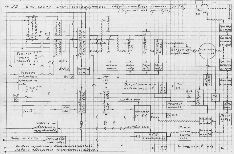
  1. As is shown in Figure 2, the gas-generating unit is exposed to vacuum generated by the vacuumizing station (see Figure 2). The vacuumizing station contains two special suction ventilators which create vacuum in the ring-shaped gas collector (38 in Figure 1) of the gas generator No. 2, overcoming the hydraulic resistance of the drop catcher, two scrubbers, and cyclone. The generator gas under vacuum flows trough the branch pipe (40 in Figure 1) to the gas collector (see Figure 2).

            In the process of gas flow, the generator gas is cleaned from solid impurities and excess moisture, and takes on the properties of ready-to-use final generator gas.

            The design content of entrainment water in the purified generator gas does not exceed 0.07 g/nm3.

  1. The installed power of all electric drives and other electrical equipment elements of the solid-fuel power-generating plant (see Figure 2) is 140.8 kW, and the consumed power is 92.2 kW.

            The volume of water required for cooling and washing the gas-generating unit is about 100 m3. Water circulates around a closed path, with trivial evaporation losses which can be replenished.

            The consumption of water for cooling the gas-generating unit is virtually not required because in the cooling jackets of the gas-generating unit and heat exchangers (see Figure 2) continuously circulates about 6.5 m3 of this heat transfer medium. Due to the heat transfer medium circulation, additionally 0.6 MW of thermal power can be generated.